Technical Guide
How to Prepare Your 3D Model for Printing
Converting a digital concept into a physical object requires more than just clicking "export." To achieve the dimensional tolerance of 0.2 mm provided by our Brisbane studio, your model must be mathematically sound and optimised for the additive manufacturing process. This guide covers the essential steps to ensure your file is print-ready, reducing lead times and avoiding costly errors.
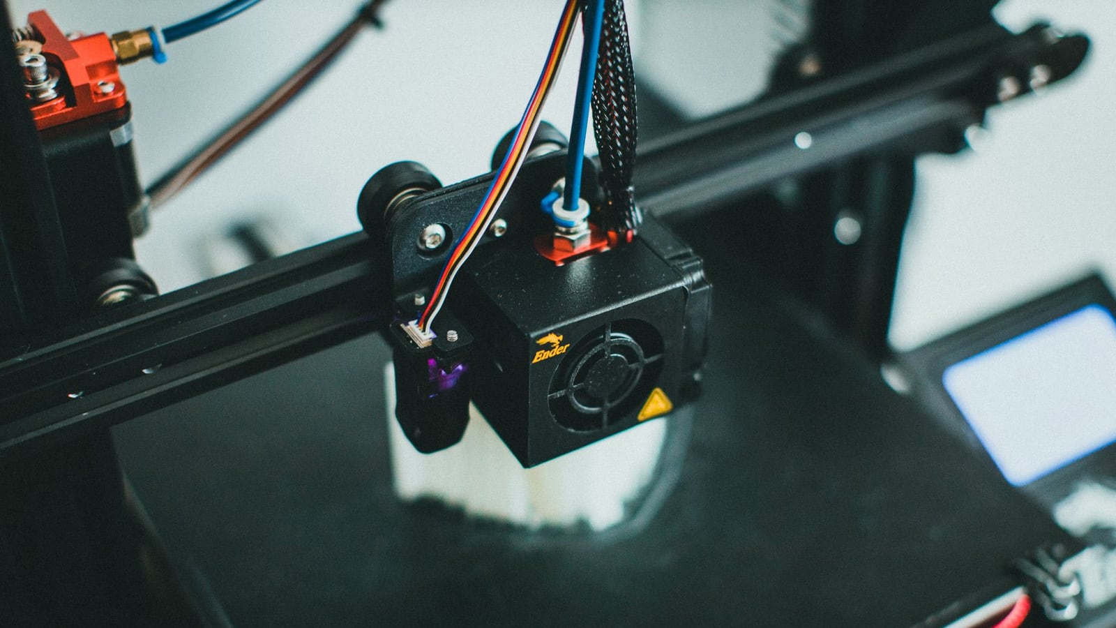
1. Ensuring Manifold Geometry (Watertightness)
The most critical requirement for any 3D print is that the model must be "manifold." In simple terms, your model must be watertight. If you were to fill the object with water, there should be no holes where the liquid could leak out. Non-manifold geometry occurs when edges are shared by more than two faces or when there are gaps in the mesh.
When a model is not manifold, the slicing software cannot distinguish between the "inside" and the "outside" of the object, leading to missing layers or random artifacts in the final print. We recommend using "Repair" functions in software like Meshmixer or Netfabb before sending your files to our FDM 3D Printing service.
2. Optimising Wall Thickness
A common mistake is designing walls that are too thin for the printer to resolve. While our high-precision machines can handle intricate details, walls that are thinner than 0.8 mm to 1.2 mm (depending on the nozzle size) are prone to warping or failing entirely. This is especially true for functional prototypes used in engineering applications across Queensland's industrial sectors.
For structural integrity, always consider the load the part will carry. If your design includes thin vertical columns, consider adding fillets or gussets to provide additional support. Remember that thin walls may appear correct in a CAD environment but can become brittle or translucent in materials like PLA or PETG.
3. Managing Overhangs and Support Structures
3D printers cannot print in mid-air. Any part of your model that extends outwards at an angle greater than 45 degrees from the vertical axis will require support structures. While Bandhdelta handles support generation during the slicing phase, you can reduce material waste and post-processing time by designing your parts with self-supporting angles.
Integrating chamfers instead of 90-degree overhangs can often eliminate the need for supports entirely. This results in a cleaner surface finish and reduces the amount of manual sanding required during the post-processing stage.
4. Choosing the Right File Format
While there are many 3D formats, we primarily work with STL and STEP files. STL is the industry standard for mesh-based printing, but it can lose precision if the resolution is set too low (resulting in "faceted" curves). For high-precision technical prototypes, we prefer STEP files, as they maintain the original mathematical NURBS geometry.
| Format | Type | Best For | Pros/Cons |
|---|---|---|---|
| STL | Mesh | General Printing | Universal / Loss of curve precision |
| STEP | Solid | Engineering | High precision / Not all slicers support |
| OBJ | Mesh | Detailed Art | Supports colour / Larger file sizes |
5. Scaling and Dimensional Accuracy
Always double-check your units before exporting. A common issue in the Brisbane design community is the confusion between millimetres and inches. Since our studio operates on a metric system, ensure your export settings are set to mm. If a model arrives at 1/25.4th of its intended size, it usually indicates an inch-to-mm conversion error.
To maintain our 0.2 mm tolerance, avoid designing extremely tight press-fits without accounting for material shrinkage. Different polymers, such as ABS, shrink more than PLA. If you are unsure about the tolerances for your specific application, please contact our team for a technical review.
6. Orientation for Strength
In FDM printing, the strength of a part is anisotropic, meaning it is weaker along the Z-axis (where layers bond). If your part needs to withstand significant stress, orient the model so that the stress is applied perpendicular to the layer lines. For example, a hook should be printed on its side rather than standing up, to prevent the layers from peeling apart under load.
Final Pre-Flight Checklist
- Model is manifold (no holes or overlapping faces)
- Minimum wall thickness is above 0.8 mm
- Units are set to millimetres (mm)
- Overhangs are optimised or supports are planned
- File exported as STL or STEP
Once your geometry is prepared, the next critical decision is the material. Depending on whether your part needs to be heat-resistant, flexible, or high-detail, the material will dictate the final success of the project. Read our guide on choosing the right 3D printing material to complete your preparation.